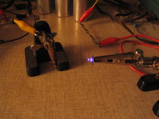
The picture above shows a corona oscillator in operation. This oscillator is capable of producing frequencies between 500 khz and 2 mhz. The visibility of the corona has been enhanced with a several second time exposure.
The Oscillator is made simply by placing the point of a pin near the head of a thumb tack.
The pin is connected to ground through a 1k resistor and the thumb tack is connected to several KV DC positive through a 1 megohm resistor.
The 1k resistor has very little effect on the circuit but drops enough voltage to make the pulse signal easy to see on an oscilloscope. The 1meg resistor mainly serves the purpose of current limiting when the pin is brought too close to the thumb tack causing an arc.
The frequency of oscillation is dependent upon the voltage, spacing between the pin point and the thumb tack head, and the strength of electrostatic fields applied near the tip of the pin. A negative field will decrease the frequency and a positive field will increase the frequency.
The frequency will also change as a charged comb is brought near the pin and thumb tack.
Interestingly, the frequency seems to have very little to do with resistance or capacitance that may be placed in the circuit.
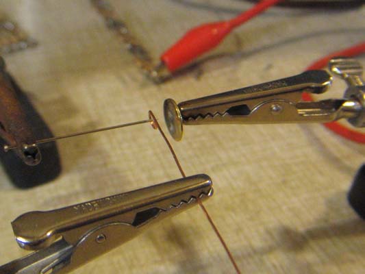
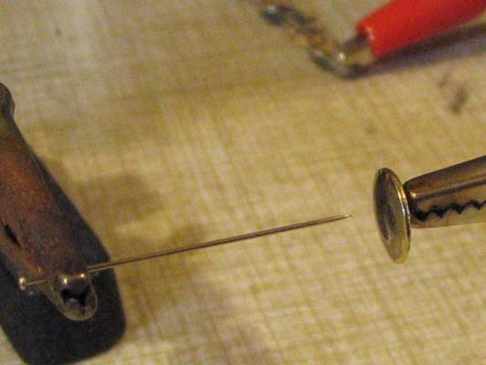
A triode can be made by placing the tip of the pin inside a small loop of wire as seen in the above picture. The loop is usually placed a small distance behind the point of the pin as can be seen in the above picture. Bringing the loop closer to the point of the pin allows the loop and a varying voltage applied to the loop to have more control over the frequency of the oscillator. When moving the loop closer to the point of the pin or beyond (between the pin point and the thumb tack) a point will be reached where oscillation and corona will cease.
The frequency of oscillation decreases as the amount of negative bias voltage applied to the wire loop is increased. As the bias voltage is made even more negative, a point is also reached where oscillation and corona will cease.
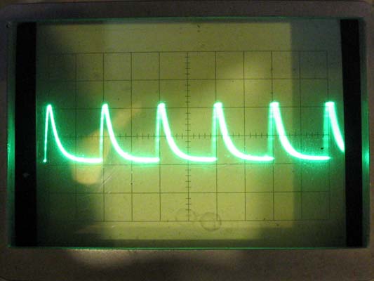
The pulses tend to stay the same width, therefore, voltage changes applied to the loop of wire also control the amount of average current flowing between the pin and the thumb tack. The amount of this current can be read at current meter I Osc.
As the bias voltage is varied over about 200 volts, there is a very big change in the plate current (I Osc) as compared to a tiny change in bias current. This amounts to a significant current gain or power gain in the triode.
This oscillator phenomenon is very consistent and seems to occur anytime a negatively charged pinpoint is brought near a positive charged plate. I am not alone in observing these pulses. They were observed and reported by Trichel in 1938. One can find his report by putting Trichel Pulses on google.