My reasons for building these homemade crt's should be obvious; certainly not to save money in building a TV set, but mostly because they emit a very intense fun field. Building these crt's fulfills one of the passions I aquired very early in life from looking into the back of a TV set many times, and watching the glow of the vacuum tube filaments and the wonderous light from the crt.
In order to be satisfied that I had really made a working cathode ray tube, I had to build device that could direct an electron beam toward a phosphor screen, and be able to at least display Lissajous figures by deflecting the beam with magnetic coils. All of these crt's did that to my great satisfaction.
These cathode ray tubes are of the cold cathode type. That is, the cathode is merely an electrode without a heater or filament. They are simply a modified discharge tube operating with ionized air at an easily attainable degree of vacuum, even several hundred microns. I do not feel that my observations of pressure are incredibly accurate but I believe I was getting the tiny 3mm dia crt to operate at pressures in excessa of 1 torr. As a general rule, the bigger the crt, the lower the vacuum pressure needs to be. I believe the large crt using the bottom of a vial inside a large glass tube, was operating at around 100 to 300 microns.
The HV power supply for these crt's was improvised using the output of a Variac into the primary of a neon sign transformer. The secondary was rectified using a high voltage diode that I found on ebay. The filter was three microwave capacitors in series. Each capacitor had its own 10 megohm shunt resistor to keep the voltage distribution across the capacitors uniform. It may also be possible to improvise a high voltage rectifier by putting several 1N4007 diodes in series. Each diode should also be shunted with a 10 megohm resistor to keep the voltage distribution across them uniform. Without these resistors, there is a tendacy for the lowest voltage tolerant device to fail first, putting even more voltage across the remaining devices. Each time a divice fails the remaining ones receive more and more voltage until they all fail.
With this power supply, it is easy to adjust the voltage between zero and about 5 kv. These crt's seemed to operate well in the voltage range of about 2 to 5 kv.
All crt's used a 1 megohm resistor in series between the cathode and the negative end of the power supply. I made a 12.5 watt 1 megohm resistor using 25 1/2 watt 1 megohm resistors soldered together in a series-parallel configuration.
When doing this kind of work, there is always the concern about x-rays. I can not assure anyone that these cathode ray tube experiments are free of x-ray hazards. I will say however, that I have read somewhere that there is not much danger of x-rays until you start using voltages above 15 kv. In all of my experiments here, I have been using between 2 and 5 kv.
I do not have the facility to make high quality sealed vacuum devices and therefore, these crt't are operated while the vacuum pump is running. I control the vacuum pressure by opening and closing a stopcock in the vacuum line. I used a standard mechanical pump as used by refrigeration servicemen and standard 1/4" flare fitting hoses. These hoses are far from what any vacuum expert would consider adequate for this kind of work.
I believe that if one were desperate and dedicated enough, one of these smallest crt's could be made to work using my simple homemade hand pump as described in the August 1966 Amateur Scientist column of Scientific american. I intend to try it soon.
There is a big misconception that says cathode ray tubes can not operate at pressures as high as these are operating because of a prohibitively short molecular mean free path. Even many highly educated physicists will tell you that a crt can not operate at these pressures. What many do not realize however, is that while the molecular (air molecules) mean free path is very short, the mean free path of electrons in the same environment is many many times longer.
I would like to put here what I call the Morris & Lee quote, an excerpt from a pamphlet I bought from them in the late 1960's. The pamphlet describes many interesting high vacuum experiments.
"The distance a molecular or atomic particle can travel is directly dependent upon the space between the stray molecules in its surroundings. For example, air molecules at atmospheric pressure can travel on the average only a few millionths of an inch before they are deflected by collision, with another molecule. At a a pressure of 1 mm Hg an air molecule can go about .002" before collision and the much smaller electrons a distance of about 3/8". At a pressure of 1 micron, these distances increase to 2" and 30 feet respectively".
Because of this, these crt's work very well at vacuum levels easily attainable by amateurs. That pamphlet was part of my inspiration to build these crt's.
Imagine a very dense asteroid field like we see in many sci-fi movies. It is easy to see that a large fast moving asteroid would most likely collide with other asteroids before traveling very far. In all these scenes however, you can always see dark space in the background. It is easy to visualise the possibility of shooting a tiny but fast bullet between the asteroids into space without hitting any of them. It would appear that many paths are available where a tiny fast object could escape the asteroid field in a straight line without hitting any of the asteroids.
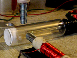
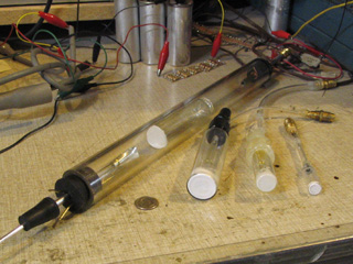
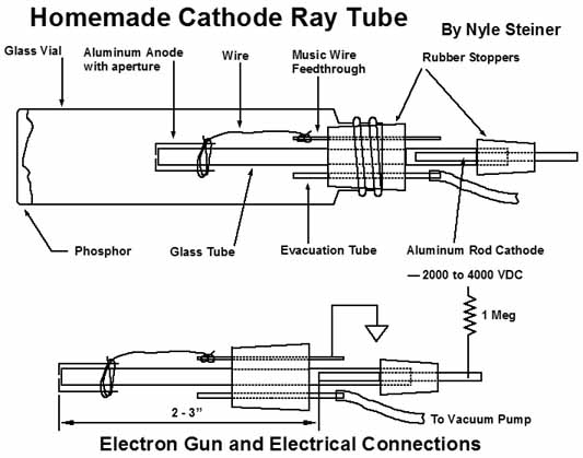
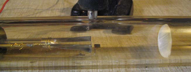
There are very few critical parameters when constructing these cathode ray tubes. The spacing between the electron gun anode and cathode was typically 1 to 2-1/2 inches in my experiments. The distance between the electron gun and the phosphor screen can vary greatly. Just keep in mind that a shorter distance will tend to make a crt with a brighter image and ability to work well at somewhat higher pressures. Notice in the picture of assorted crt's that one crt was built from a 1" diameter glass tube. The screen was a glass vial, that fit loosely inside the tube. It's outside bottom was painted with phosphor. The bottom (screen) of this vial faced toward the electron gun and the image on the screen was best viewed from the same side as the electron gun. The distance between the screen and the electron gun could be easily varied merely by tipping the whole crt and sliding the vial from one position to another.
The electron gun is nothing more than a small diameter discharge tube that has a small aperture in the positive anode. Electrons traveling toward the positive anode are moving fast enough that they travel right through the small aperture forming an electron beam. If the evacuated space extends beyond this aperture, you have a cathode ray tube. Thats it!!! Electrons traveling through the aperture into the evacuated space beyond strike whatever is in their path whether it be the wall of the vessel, some phosphor, piece of paper, metal or whatever. The electrons always seem to find their way back to the positive anode that they left behind.
This beam of electrons can be easily deflected with a magnetic field from either a nearby magnet or a current carrying coil. I did manage to produce a deflection with an electrostatic plate but things are different in this respect from the commercialy made crt's, when the plate is in an ionized gas. More on this later.
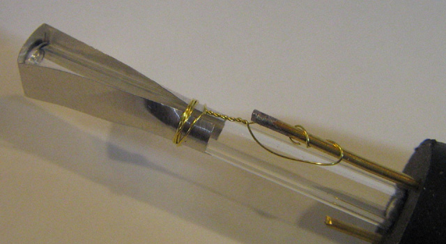
I made most of my electron guns from 5 or 6mm outside diameter standard wall glass tubing. The positive anode (in the picture above) can be a strip of thick aluminum foil (cut from an aluminum pie plate) with a small hole punched in it. After folding the foil around the end of the small glass tube, the hole can be punched with a pin where it covers the end of the tube. The anode can also be a very small diameter metal tube. I also made an electron gun by simply constricting the positive end of the glass tube and placing the positive anode elsewhere in the crt.
The cathode (not visible) can be a 1/8" dia. aluminum welding rod sealed (any way you find handy) in the opposite end to the right. Note: It is best to use aluminum for the cathode in order to minimize sputtering, a process where metal atoms fly away from the cathode and coat the inner wall of the glass tube. This shortens the life of the crt. Aluminum has a very low sputtering rate as compared to other metals such as copper or silver.
Electrical connection terminals through a rubber stopper can be made using 1/16" dia. or smaller, welding rod or music wire. Just put a piece in a drill and, being careful not to also penetrate your fingers, drill it through the rubber stopper.
This assembly using the rubber stopper (just visible in the picture), can be stuck into one end of a much larger (1" dia.) glass tube or the mouth of a glass vial. The diagram below shows how to make a glass vial into a crt. Before inserting the electron gun into the mouth of the vial, I took a little phosphor powder (from the broken fluorescent light), mixed it with some water and swished it around inide the bottom of the vial until it dried.
Every crt has an optimum vacuum level at which it operates best. The optimum vacuum level is always the highest level of vacuum (lowest pressure) that can be achieved before the discharge in the electron gun ceases. With every discharge tube, the discharge will cease when the pressure gets to a low enough level. A smaller diameter discharge tube will cease operating at a higher pressure level than a larger diameter discharge tube. Therefore, a crt with a smaller diameter electron gun must operate at a higher pressure than one with a larger diameter electron gun. A crt with the smaller diameter electron gun would thus typically end up being a smaller crt because of a higher operating pressure and shorter travel distance for the electron beam.
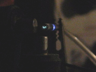
There are many materials that will produce a glow where they are struck by the electron beam. If the room is darkened, a blue spot can be seen where the beam hits the walls of the glass vessel.
For the face of most of my crt's, I used some phosphor powder salvaged from a broken fluorescent light that fell on the floor several years earlier. After some very choice words, I realized the opportunity to acquire some phosphor that I had always wanted to experiment with. The phosphor is a fine white powder that can be easily scraped from broken pieces of fluorescent light glass. It takes only a very tiny amount of this phosphor to make a cathode ray tube. This powder of course is one of the best materials to use for a crt face as it is designed for this very purpose, to fluoresce when bombarded with electrons. I simply mixed some of this powder with water and applied it to the inside face of the crt and let it dry.
YEA YEA YEA!!! I am already aware of most of the toxic hazards of fluorescent lights but feel however, that these hazards are less severe than most of the hazards we face daily in our lives. I should say though, that anyone taking phosphor from a fluorescent light do so at their own risk. I have my opinions but I am certainly not an expert to give advice about the toxic hazards of fluorescent lights. I will say that since an early age, I have heard many times, never to get a cut or scratch from a piece of a broken fluorescent light.
I also found that a piece of paper painted with a highlight pen made a usable screen if the lights were very low. This could be an advantage if you are trying to impress your girlfriend. This screen as one might expect, worked best when viewed from the same side as the electron gun. This paper screen however, soon aquired a brown burn like spot where the beam would hit most of the time. I would suggest trying a flat piece of ceramic material painted with highlight pen to make a screen. That might work well as a rear view screen but I didn't try it for lack of a flat piece of ceramic.
Clorox laundry bleach powder will fluoresce in the electron beam. I havn't tried doing this but, if this powder were to be ground very fine and mixed with water into a paste, it might make a usable screen phosphor. The highlight pen and bleach powder do not seem to fluoresce as well in the electron beam however, as they do under the influence of ultraviolet light.
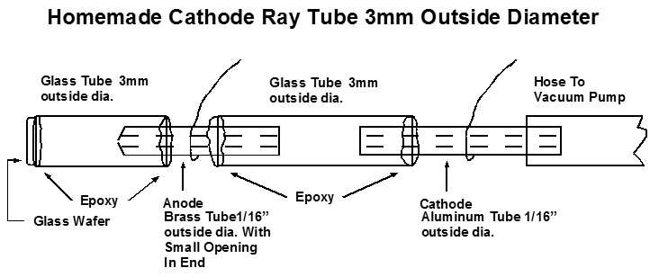
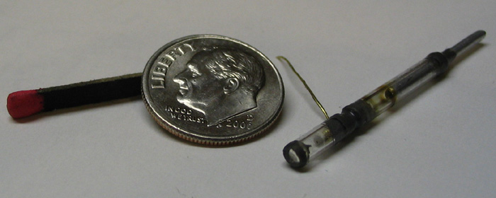
With the 3mm crt, the spacings, between the anode and screen and between the cathode and anode, are somewhere between 1/8" and 3/16".
The screen was made by heating a glass tube in a flame and pulling it to a fine thread. After breaking the thread in two, it was fed into the flame to form a small sphere. The sphere was then taken out of the flame and pressed into a wafer shape between two microscope slides before it cooled. I had to try this about four times to get one that did not break after cooling and breaking off the remaining thread. This wafer was then epoxied on to the end of the 3mm diameter glass tube.
A tiny amount of phosphor powder can be dropped into the front end before epoxying the anode in place. Shaking the crt around with the face down will apply the phosphor to the screen.
The electron gun anode was a piece of 1/16" o.d. brass tubing about 3/8" long. The end facing the screen was made into a tiny opening. This was done by putting the piece of tube in a hand drill and spinning the end against a piece of steel.
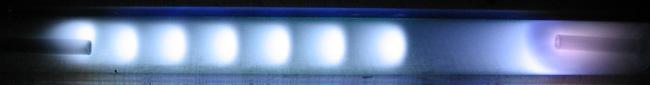
When running these crt's they typically act as follows. The high voltage is turned on and the vacuum pump is started. Very quickly, the electron gun (discharge tube) starts to glow. As the pressure gets lower, striations form in the electron gun. As the pressure gets lower, the striations get larger and fewer and they will be near the positive anode. At the point of almost having no striations, a faint but fuzzy glow will start to be noticeable on the crt screen. The pressure is now getting just low enough that some of the electrons coming through the anode can make it to the screen. As the pressure gets still lower, the spot on the screen will become clearer and much brighter. The crt is now operating at the optimum vacuum (pressure) level. I always keep it at this point by turning a stop cock, between the crt and the pump, on and off. When the pressure gets still lower, the glow discharge in the electron gun will cease entirely and everything including the screen goes dark. Closing the stopcock will allow the pressure to start rising again and the spot on the screen and the electron gun will light up again.
It is easy to notice light from the electron gun hitting the screen and interpret that as the electron beam spot. You can verify that the spot on the crt face is the real deal by putting a magnet near the crt. You should be able to move the spot around very easily with a magnet.
You can put coils near the crt to deflect the beam electronically. Placing a permanent magnet at the right distance from the crt and in the right position, can act as a centering control.
Even though these simple crt's lend themselves to the use of magnetic deflection, I succeeded in producing vertical deflection using an electrostatic deflection plate. I did not put a lot of effort into this so It would not be surprising to hear of someone getting different results than what I will describe here.
In all of my crt experiments I connected the electron gun positive anode to ground and the electron gun negative cathode through a 1 megohm resistor, to a negative dc voltage of several kv. All voltages applied to the deflection plate were relative to the ground potential of the positive anode.
I drove this plate with the sound of an analog synthesizer using an audio amplifier output to a step up transformer. A negative bias voltage of 200 to 300 volts was applied in series with the output of the step up transformer so that the audio could deflect the beam through both negative and positive excursions. Using a 60 hz driven horizontal coil, the audio could be viewed much like you would see it using an oscilloscope. You can view a video of this experiment at youtube.com. Just search for Homemade Cathode Ray Tube and Oscilloscope.
An electrostatic deflection plate behaves somewhat differently in an ionized gas than it does in an ultrahigh vacuum as is used in commercially made crt's. The ionized gas tends to act as a conductive shield against the effects of an electrostatic field from a grid or plate. I found this out when experimenting with homemade vacuum tubes. Whenever the inside residual gas was ionized, the grid had no effect on electron flow between the cathode and plate.
In a commercially made crt, an electrostatic deflection plate will push the electron beam away from it when a negative voltage is applied and pull the electron beam toward it when a positive voltage is applied.
In the case of these cold cathode crt's however, I observed that with a negative voltage applied to the plate, the beam was deflected away from it as expected. With a positive voltage applied however, no deflection was observed. Instead, the applied positive voltage to the plate had a tendacy to sharpen the focus of the beam. The positively charged plate did not have to be anywhere near the electron beam in order to tighten the focus. The positively charged plate could be almost anywhere in the crt.
Whenever a negative or a positive voltage was applied to the deflection plate, a small current would flow between the plate and the anode.
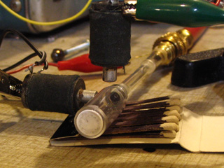
At first glance the picture above may look peculiar. The vertical deflection plate on the bottom and the horizontal deflection coil on the top appear to be opposing each other. This is the way it should be however because the electrostatic plate deflects the beam directly away while the magnetic coil deflects the beam at a right angle.
I had little success with the use of both vertical and horizontal deflection plates. That is why I used a horizontal deflection coil and a vertical deflection plate in this experiment. I believe that I once read somewhere online that Braun the inventor of the cathode ray tube, had similar results when trying to use electrostatic deflection with his cold cathode crt's.