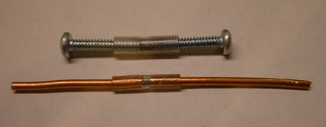

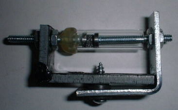
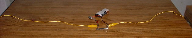
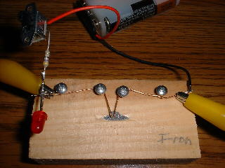
Lower picture above shows coherer made with iron filings in a glass tube. Electrodes are screw heads filed flat and reduced in size to just fit inside the tube. All three coherers shown above work very well.
It turns out that making a coherer, that works impressively well, is easy. I had success using just ordinary materials around the house. Its operation can be observed using an ohm meter and a source of activation. When one of these coherers is working well, a spark coil can activate it from across the room and cause its resistance to suddenly drop to a very low value. It can be deactivated (returned to the very high resistance state) with a slight mechanical tap. The coherer can also be activated by holding a small piece of metal and touching one of the pickup wires with it.
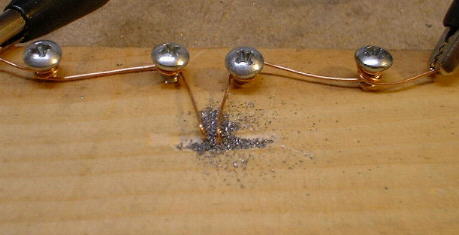
My first attempt at making a coherer was to make it inside a piece of glass tubing, as described in vintage radio books. It was filled with nickel filings and was somewhat successful. I soon realized that I could make good working coherers by merely gouging a hole in a piece of wood, filling it with metal filings and connecting two pieces of copper wire for electrodes. Two good iron filing coherers were also made by inserting screws or copper wire into the ends of short pieces of flexible vinyl tubing. The glass tube coherer mentioned above was emptied and refilled with iron filings to make a good working coherer (see pictures above).
I tried using filings from different metals, namely copper, iron, nickel and aluminum. All of them worked. Some of the most impressive results have been obtained from iron filings and screws or copper wires for electrodes. The iron filings were obtained by filing a nail that was held in a vise. The filings were collected by brushing them from the top of the vise onto a piece of paper (see pictures above).
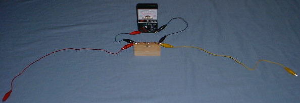
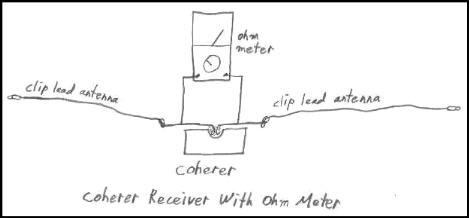
Since the iron filings coherer works well with 1 1/2 volts across it, I was able to make a receiver simply by connecting an ohm meter across it and attaching two clip lead wires to pick up the signal. A signal from the transmitter causes a very high ohm meter reading to drop to a very low value. The receiver could be reset and made ready to receive another signal by tapping the coherer, returning the resistance to a very high value.
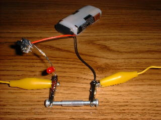
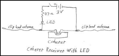
Another receiver that worked very well was made by connecting an LED and 3 volts across the coherer. A signal from the transmitter causes the LED to turn on. Tapping the coherer turns the LED back off. See the photos and diagrams. I was able to activate both receivers from a distance of greater than 20 feet using the transmitters described.
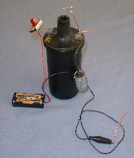
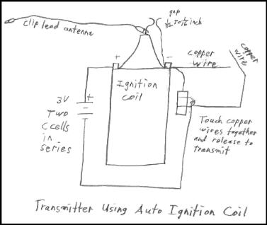
A transmitter was made by using an auto ignition coil as shown in the diagram. Even though the ignition coil is intended to be used with 12 volts, it will operate with less. With just two AAA cells connected in series, I was able to get a small spark, capable of activating the coherer from a distance of greater than 20 feet. A shorter spark gap that produces a quiet spark, seems to be able to actuate the coherer at a much greater distance than a longer gap that makes a bright noisy spark. I am not sure why but a book published in 1906 said the same thing. The spark gap can therefore be adjusted for optimum transmitter performance.
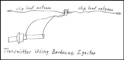
Another type of transmitter was made by attaching two clip leads to a barbecue piezo ignitor and supporting them with a dowel. The leads were attached so as to form a 1/8" to 1/4" spark gap in the middle. This transmitter could activate the iron filings coherer from a distance of greater than 20 feet whenever the button was pressed.
With the iron filings coherer, the ohm meter (2000 ohms/volt) worked well on R x 10, R x 100 and R x 1k. When the iron filings coherer was working well, the ohm meter indications would jump from essentially open to about 20 ohms when a signal was received from the transmitter.
A coherer made with copper filings from a piece of copper pipe, also worked well. The ohm meter indications from the copper coherer would go from essentially open to about 400 ohms.
![]()

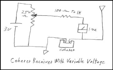
One important point to remember when experimenting with coherers is that the voltage across them when they are open, can not be too high. After all, it is a voltage level that sets them off. With some of the coherers that I made, I found it necessary to keep the voltage across them as low as 1/2 volt. Too high a voltage and they will not turn off when tapped. The diagram below shows how a coherer can be used with lower voltages across them. Since the iron filings coherer worked very well with 1 1/2 volts across it, the ohm meter configuration worked well with it.
Some coherers, when tapped, seem to turn completly off (open circuit), while others may just return to a higher resistance value. A coherer that will not turn completely off or not turn off at all when tapped, may be a sign that the applied voltage across it is too high. The nickel filings coherer had the tendacy to not turn completely off when tapped, wheras the copper and iron cohers, when working well, would turn off to essentially an open circuit. The iron filings coherer so far is my favorite as It was as sensitive as any, able to drop to a few tens of ohms when actuated and return to open circuit when tapped.
The strength of the actuating signal can often affect how hard the coherer turns on. A strong pulse may make the coherer turn on at a much lower value of resistance than a weaker pulse. I have also observed occasionally, only when receiving weak pulses, that a coherer can be partially turned on with one pulse and somewhat back off again with a later weak pulse. I have never yet observed any tendacy for a coherer to turn off from a strong pulse.
It seems that coherers respond to the amount of current that flows through them. In other words, each given amount of current through the coherer will cause the coherer resistance to drop to a specific value. Thus it would appear that tiny rf pulses from a spark coil across the room or a distant transmitter, do indeed cause current values in the milliamp range to flow through the coherer even though it may be for only a few microseconds or perhaps even nanoseconds.
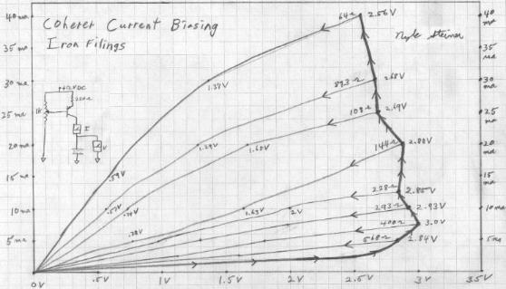
The graph below shows voltage readings, measured across the glass tube iron filings coherer, plotted against various amounts of applied DC current from a variable DC current generator. The heavy line with arrows pointing to the right and upwards is a set of voltage readings taken across the coherer as the current through it is steadily increased from zero to 40 ma. If at any chosen point along this line we decide to reduce the current again, we will get voltage readings that form a line with arrows pointing downward to the left. Lines with arrows pointing downward to the left tend to be consistant and voltage readings obtained from varying the current anywhere along any of these lines are quite repeatable as long as the applied current does not exceed the highest applied current value since being tapped. As soon as a current is applied that exceeds the point at the right end of a line (with the arrows pointing downward to the left), the coherer will drop to a lower resistance value and create a higher line (arrows pointing downward to the left).
The coherer is very stable for any given applied current but very unstable when applying hard voltages. An applied voltage is unstable because it causes a given current to flow, setting the resistance lower which in turn causes a higher current, which in turn causes a lower resistance etc.
As can be seen on the plot, the coherer resistance (represented by one of these lines with the arrows pointing downward to the left), can vary somewhat with the applied voltage.