The output power of this homemade flame triode is very small and probably offers very little in the way of practical use. I found it exciting however, to observe that this simple homemade device can exhibit gain. Some support for the idea, that this device exhibits gain, was afforded by successfully building a dual triode free running multivibrator oscillator.
A piece of iron or steel that has had table salt applied to it and and another clean piece of iron or steel will form a rectifier when put into a propane or alcohol flame. I wrote an article about making a flame detector for a crystal set in the March1,1997 "The Xtal Set Society Newsletter" Volume 7, No.2. This detector used a propane flame and a salted cathode.
In the past, I have experimented with electrical conduction within propane flames but recently started experimenting with denatured alcohol flames. The denatured alcohol flame is cooler and allows the cathode to have a much longer lifetime however, the amount of current flow through the alcohol flame is usually less.
More recently, I have tried applying Potassium Bitartrate (Cream of Tartar from the kitchen) to the cathode instead of salt. This increased the connductivity of the flame rectifier by many times. With a Potassium Bitartrate treated cathode and a steel anode in just an alcohol flame, it was easy to rectify 120 VAC into a DC voltage sufficient to run a neon bulb relaxation oscillator.
I suspect that the increased conductivity might have something to do with potassium because potassium ferricyanide and potassium hydroxide also work well as a cathode material. I want to try making a comparison between sodium chloride (table salt) and potassium chloride as soon as I can get some potassium chloride.
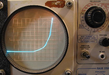
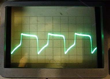
The above curve tracer picture shows the curve when AC voltage is applied across a rectifier made with an alcohol flame. In this picture, the current (vertical) is 10 microamps per division and the applied voltage (horizontal) is 20 volts per division. The center of the curve tracer screen represents zero voltage.
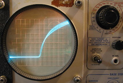
This second picture shows the curve when AC voltage is applied across a rectifier made with a hotter propane flame. The current (vertical) is 5 milliamps per division and the applied ac voltage (horizontal) is also represented by 20 volts per division. In this picture you can just barely see the dot on the current sensitivity knob set at 5 ma. The center of the curve tracer screen also represents zero voltage in this picture. Although the forward voltage drop is high, this propane flame diode is able to carry 40 milliamps forward current!!
If the anode is kept cool by making it large and having heat sink capability, the reverse breakdown voltage of an alcohol flame rectifier can be kept quite high. Using a variac driven neon sign transformer into this rectifier, I was able to observe a peak reverse breakdown voltage in excess of 2 KV. One one occasion, a flame rectifier was withstanding up to 4 KV peak reverse voltage. I found the flame rectifier however, to be more reliable as a 2 KV reverse breakdown device.
With the 2 KV reverse breakdown voltage, I was able to charge a power supply capacitor up to 1 KV (the rectifier must withstand the reverse AC voltage cycle in series with the charged capacitor).
While playing with the alcohol flame, I noticed some very intriguing characteristics. Most articles about flame conduction, flame speakers etc, talk about how the salt on the cathode puts ions into the flame to make it conductive. In the case of my alcohol flame experiments, I found that the flame seems to conduct current even when the anode is not placed in the ionized part of the flame. Even if the salted cathode is placed in the very top of the flame, there is still current flow when the anode is placed in the very bottom of the flame.
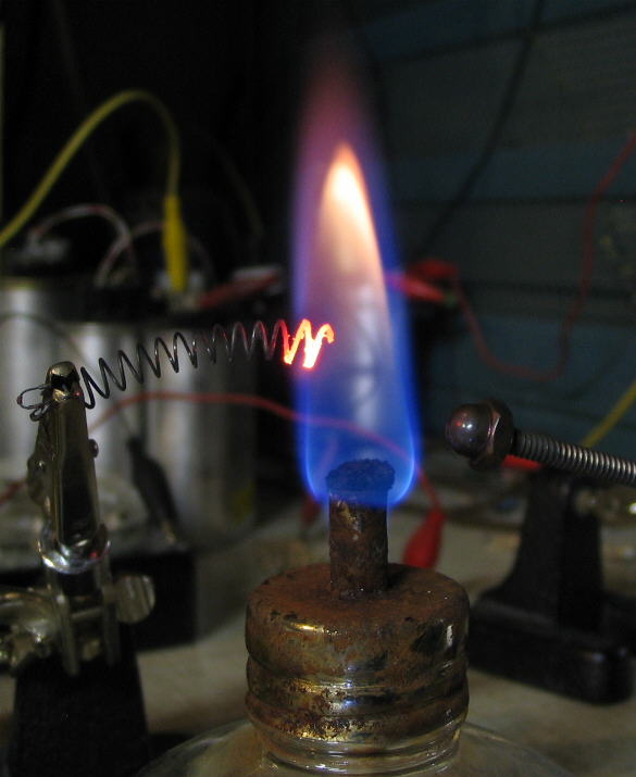
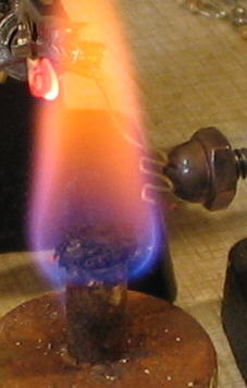
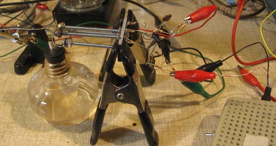
What I find even more intriguing is that current can still flow even when the anode is up to 1/8" outside of the flame. The picture below was taken while current was flowing and in low light to better define the edge of the flame. The anode which is a 6-32 cap nut, clearly appears to be well outside of the flame. The cathode on the left is a piece of steel spring that was previously dipped in Cream of Tartar.
I presently can not offer any good explanations for this phenomenon. Perhaps a flame has an invisible outer layer of some kind that we can not see. Perhaps the cathode and flame together form some kind of super cathode that can shoot electrons out through air at atmospheric pressure. Or - perhaps the mean free path of electrons in air is much longer when the air is hot. I don't have any data on the hot air theory but it will be interesting to look into.
I will keep this article updated if I can find out more about this phenomenon
Numerous times I have experienced disappointment in observing that a grid placed between a cathode and anode in any kind of ionized conductive gas or flame, can not control current that is flowing between the cathode and anode. This also seems to be common knowledge and I believe it is because of the ionized conductive atmosphere around the grid acting as an electrostatic shield.
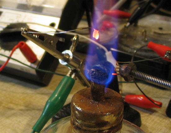
I have found however, that with the positive anode placed outside of the flame, a grid placed within the space between the flame and the anode can control the amount of current flowing to the anode - making a triode with gain. I believe I have been able to observe both power gain and voltage gain with this flame triode. I find that this flame triode closely resembles a vacuum tube triode. The grid is a very high impedance input that allows an applied voltage to control the amount of electron current flowing from the cathode (inside the flame) to the anode (outside of the flame).
The grid in the above picture is made of 28 gauge galvanized steel wire.
What is gain anyway. There are different ways that gain can manifest itself in a circuit. The ones I am most familiar with are Power Gain, Voltage Gain, and Current gain. My approach to gain evaluation as described below is crude and simplistic but I believe that it produces sufficient evidence with a good margin for error, that this flame triode exhibits gain. Exactly how much gain? I would expect data, taken by those who are truly competent, to be quite different but still positive.
The schematic below shows how current flow and applied voltages can be varied and measured. The applied B+ voltage was somewhere between 100 and 150 VDC. When the grid voltage was changed from zero to approx -20 volts, as measured by volt meter V, the grid current, as measured by current meter I Grid, changed an almost imperceptible fraction of a microamp. An analog meter was used so it is difficult to tell accurately the exact amount of grid current change. This change in grid voltage caused the current through the load resistor RL to change about 6 micropmps as measured by current meter IL.
Lets say that the grid current change was .3ua (I feel safe in saying that it was not more than that). A 20 volt input times .3 ua calculates to 6 microwatts. A 6 microamp change in the current through RL (if RL = 10 meg) calculates to be a minimum power dissipation change of 360 microwatts from RL. This appears to be a power gain of around 60.
If RL = 1 megohm, the power dissipation change from RL would appear to be around 36 microwatts. This appears to be a power gain of around 6.
No doubt there are other factors in determining power gain in a circuit and the evaluation here is simplistic, but I think it is a reasonable assertion to say that this flame triode exhibits power gain when an input power change of 6 microwatts can cause at least a 36 microwat power dissipation change elsewhere in the circuit.
Since there was a tiny noticeable change in grid current we could perhaps view this device as we would a bipolar transistor and say that it showed a beta of 20.
I intend to check further into these evaluations and will post appropriate updates.
The schematic below shows how an applied audio signal (in my experiments a sawtooth wave), applied to the grid, can be amplified. I found that the amplifier worked best when no bias voltage was applied to the grid. A 1.8 volt pp signal applied to the grid would appear as a 3 to 4 volt pp signal at the anode.
As with a vacuum triode amplifier, the sawtooth input signal was inverted when viewed at the anode output.
Since the anode load resistor is so very high, it is necessary to use at least a 10x scope probe when observing this circuit. Voltage gain in this circuit was clearly observed to my satisfaction using a 10x scope probe but I decided to further reduce the possibility of misinterpretation caused by scope probe loading, by making circuit observations through a 100 megohm to 100 kohm voltage divider connected to the input of the scope. The scope sensitivity had to be cranked up to 5 millivolts per division but the scope loading on the circuit was now 100 megohms. With both the 10x probe and the 100 meg divider, I was able to observe voltage gain in this flame triode.
It goes without saying that the thrill factor from making this flame triode experiment, would be greatly heightened if I could use it to build a circuit capable of actually doing something. I accomplished that by making a dual triode and building a multivibrator oscillator circuit. I was also able to use this circuit as a code practice oscillator by inserting a key in series with the power supply and coupling the output to a small audio amp.
See my links section for a video of this circuit in operation.
A multivibrator oscillator is a well known circuit consisting of two triode amplifiers, each with its output capacitively coupled to the input of the other. Since the phase is inverted in each stage, positive feedback is achieved, forming an oscillator.
The picture below shows a dual triode arrangement that uses a common cathode (left part of flame) for both grids and plates. The screws supporting the plates (cap nuts) and the wire grids are made long to keep heat from melting the plastic that supports them.
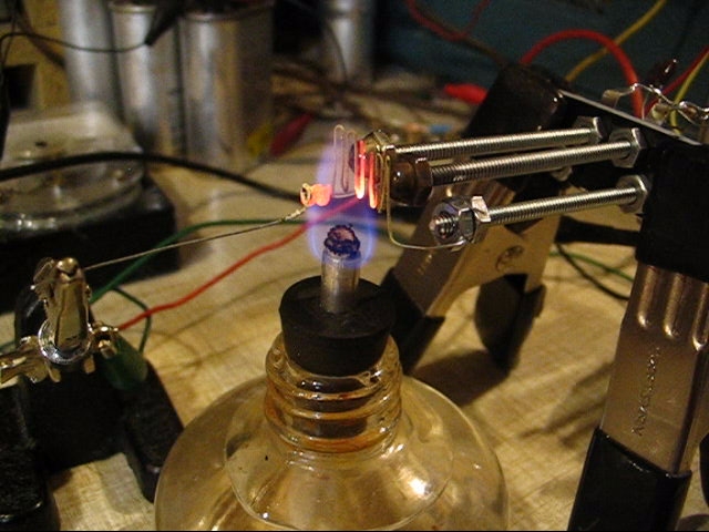
Oscillator output can drive a small audio amp, visible at right end of above picture.
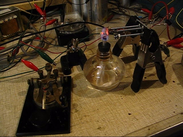
Code practice oscillator is made by putting a key in series with the power supply.
Sparkbangbuzz Home Page.