
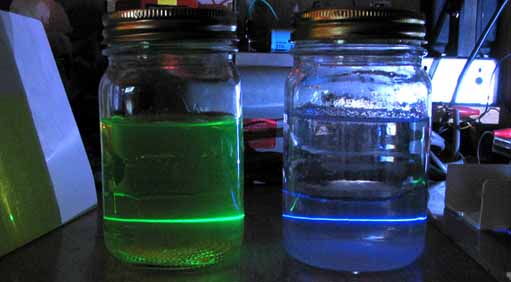
Upper picture: An ultraviolet beam from a T.E.A. laser is striking a piece of paper covered with highlight pen ink. Lower picture: An ultraviolet beam from a T.E.A. laser (partly visible on the far right) passes first through the bottle on the right (water with laundry whitener, blue glow) and then continues through the bottle on the left (water and highlight pen ink, green glow) until it strikes a piece of paper (covered with highlight pen ink, green spot).
When I read about TEA lasers recently though, that all changed. Here is a laser that is built from aluminum foil, a dielectric and some pieces of aluminum. It is amazing to think of a laser project where a simple 4 to 6 KV DC power supply is the most elaborate component.
Why I am building TEA lasers can be explained very simply: There is a great deal of satisfaction in the idea of having built your own laser. These lasers are fascinating and they emit a very powerful fun field in addition to their ultraviolet beam.
In spite of the simplicity, the idea of building a TEA laser of my own seemed very intimidating. After all, it is a laser and some of the conditions necessary for it's operation are very extreme. A high voltage transition must be faster than several nanoseconds and the capacitors have to have extremely low inductance values in order to get that kind of speed. I had the concern that my lack of expertise in the field of laser technology would make it difficult for me to solve any problems if it didn't work.
As it turns out however, all of these extreme conditions are very easy to produce. It did not take long to get a laser working reasonably well. My wife may not agree but, I find that it easier to make a working TEA laser than it is to make a batch of cookies.
There are two main objectives in mind as I write this article. One is say that yes, the TEA laser also works for me even though I am not an expert in laser technology.
The other objective is to demystify the homemade TEA laser and address many of the concerns that I was plagued with in the beginning such as: How critical is the electrode rail alignment? What if I make the foil plates the wrong size? Just how straight must the laser electrode pieces be? What happens if I don't make the laser the right length? What types of dielectric material will work? How much voltage is really required? Must it be filtered? Will an AC supply work? What about the polarity of the voltage applied? How can you possibly make a spark that jumps between two long electrodes, cover their entire length?
This article is mostly a detailed description of things that I found to work well. Not being a laser expert, I would recommend reading the professors web site (in my links section) or similar material for more details on how TEA lasers work and their characteristics. If I understand it right, TEA stands for Transverse Excitation at Atmospheric pressure. What is being Lased? It is just plain air and yes, at atmospheric pressure. Air must be very good for building lasers because it is classified as super radiant, meaning no mirrors are required to get laser action. We are breathing a very good laser material.
TEA lasers produce a beam of ultraviolet light in very short pulses but I have managed to run them at a rep rate of up to 120 hz, making them appear continuous.
The ultraviolet output can easily be seen when it strikes UV fluorescent materials commonly found around home.
The most critical part of making a TEA laser is in making the capacitors. According to what I have read, the inductance inherent in these capacitors must be very low. Using too thick of a dielectric will cause too much inductance for the laser to work. Aluminum foil plates works as well as anything. Don't worry about having pieces of sheet aluminum cut. The aluminum foil plates tend to cling to the dielectric, making thin, tight, low inductance capacitors. Once you have these foil capacitors made as described here, you can get many different strips of metal (usually aluminum) to work well as the laser electrode rails.

Start with a flat piece of particle board approx. 8 1/2" by 12"

Cover this board with aluminum foil. This will be a common electrical ground plane. Let the foil hang over the back edge as shown. This will make it easy to connect to the power supply ground.

Lay the plastic dielectric on the foil as shown. Notice that a section of the base foil (right end of picture) is not covered by the dielectric. This section of foil is left bare in order to make contact with the spark gap assembly.

Lay two 3" X 10" pieces of foil as shown so that there is approx 1/8" of space between them. To prevent unwanted arcing, the edges of both pieces of top foil should never be less than 1/4" from the edge of the dielectric whenever base foil is directly beneath. This is now a basic TEA laser base consisting of two capacitors.
At this point you can add any laser electrode rail configuration that you choose whether it be angle aluminum, rod, bars or even combinations of different shaped pieces. Below, I will describe some that I have tried.

The above picture was also taken after a considerable amount of operating time on the laser. The dielectric is clear but notice how it has turned frosty white near the edge of the top aluminum plate.

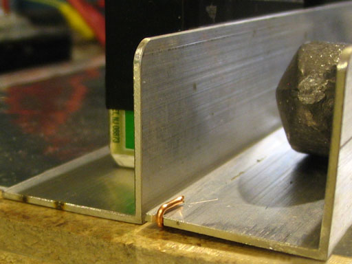
This flat vertical face of aluminum will be one of the laser electrode rails. The other laser electrode rail will be a piece of aluminum with a thin edge facing this flat wall, typically, at a distance of approx 1mm and raised slightly so as to not touch the dielectric. I call this the "against the wall" configuration. This is unlike most other TEA laser electrode configurations I have seen which have a thin edge on both sides.
I really like making TEA laser electrodes this way. This method is very versatile and I have been getting great results from it. From my observations, this "against the wall" type of laser electrode configuration works as well or better than traditional configurations I have tried, that use a thin edge on both sides. This configuration allows you to experiment with many different shapes and sizes of thin edge material to face against this vertical wall of aluminum. Pieces shorter or longer than this basic 10" angle aluminum wall will work as a laser as long as they don't overlap the dielectric at a point causing a short.

I put one end of a piece of 18 gauge (.040) bare copper wire one foot long, into a vise and stretch hard from the other end until it is very straight. Thicker wire will also work well if you can get it straight. I then put it on the bottom of the angle aluminum piece about 1/16 " from the edge. I file a small notch about 1/16" from the edge, in each end of the angle aluminum. This allows the wire to be bent around the ends holding it in place.


The two electrodes are now each sitting on top of a separate piece of foil and are at this point electrically insulated from each other.


The laser is very stable. Once the electrode spacing is adjusted, it will usually stay that way for long periods of use.
An obvious improvement though, would be to make some kind of screw adjustment on each end. I hope to get around to trying that soon.


Left picture: A resistor can simply be laid across the two angle aluminum strips. No physical attachment is necessary. The laser works just fine with the resistor just sitting there. The resistor value is definitely not critical and can be anything between 1k to 1meg. A value of around 100k is my choice because it allows the laser to operate at reasonably high rep rates without much possibility of effecting the laser operation in any way.
Right picture: As an alternative to the resistor, a handmade coil of approx 20 turns can be laid across the two sides. As far as I have been able to observe, there is no difference in performance when using the resistor or the coil. Personal preference would play the biggest part.
I made the laser work quite well at a very high rep rate(120 Hz) by running the laser straight from the NST with no series resistor or rectifier. This made the 100k resistor start to burn up. In this situation, the coil was a better choice. At lower rep rates, there is absolutely no problem with the resistor.


The spark gap assembly is a 6-32 x 3/4" screw put through a piece of 1 1/2" long angle aluminum. A cap nut is put on the end of the screw. The spark jumps between ground and another 1 1/2" piece of angle aluminum sitting on top one of the foil plates. With the foil plates being the same size as I have made them, there is little difference which side of the laser the spark gap is on. Contact with the ground foil and mechanical stability are enhanced by putting a weight on the spark gap assembly. The gap is adjusted by sliding the assembly until a spark jumps regularly. I usually get best results when the gap is between 1/16" and 1/8" wide.


At first the idea of building a homemade TEA laser seemed intimidating in spite of it's simplicity. I was plagued by many questions. Below is an attempt to answer many of them using my observations and experiences.
I take no responsibility for safety in this project. If you build this laser, you do it at your own risk. I personally feel however, that working with this laser is less hazardous than going shopping if proper precautions are taken. That is only my opinion though. Below are some thoughts and suggestions about safety.
The most obvious safety concern would be the high voltage that is used. When using a one megohm resistor in series with the power supply, safety can be improved by having the resistor away from the laser. This will limit the amount of current that can flow through you if you accidentally touch the wrong parts.
This laser also produces ozone. There are some who will tell you that ozone is detrimental to health.
I can not tell you for sure that this device is free of x-ray radiation. I have never heard of anyone having any problems with x-rays while doing open air high voltage experiments, especially when the voltage is below about 15 kv.
Care should be taken to make sure that the beam never hits your eyes. Extra care should be taken since the beam is invisible ultraviolet light.
When working with this laser, hearing protection should be worn. The sparking from this laser produces very potent pops that are very loud and irritating. I can't imagine how exposure to them could be anything but strain on your hearing.
I have found with my TEA lasers, that power supply polarity makes little if any difference.
Any power source that can charge the capacitor part of this laser up to 4 to 6 kv can be used. I have been using a NST (neon sign transformer) with excellent results. I normally use a high voltage rectifier in series with a 300k to 1megohm resistor. No filter capacitors are needed. Safety is better when no filter capacitors are used.
It is great to have a Variac driving the input of the NST so that many levels of HV can be tried.
A good resistor can be made by connecting five 1/2 watt 1meg resistors in parallel. Make five of these parallel configurations and put them in series (a total of 25 resistors). You now have a 1meg 12.5 watt resistor that can be tapped for different values.
I found some high voltage rectifiers on ebay but one for this task can be made by putting 15 1N4007 diodes in series. Each diode should also be paralleled with a 10meg resistor. The resistors are needed to equalize the reverse voltage drop across the diodes. I have been using one that I made this way for rectifying 6kv and have had no problems.
Each 1N4007 is good for 1kv reverse voltage. Why then am I using 15 of them to rectify 6kv? If the laser capacitors are charged up to 6kv then the diode sees double that amount on the reverse unused portion of the cycle. During the reverse cycle, the transformer voltage and the charged capacitor voltage are in series across the diodes.
I have also been able to run TEA lasers that are directly connected to the output of the NST using no series resistor or diode. The laser when connected this way will pulse at 120 hz since it is firing on both the negative and positive half of the 60 hz ac high voltage. I believe however that the dielectric is under the greatest stress when running at this rep rate so I tend to run them at lower rep rates using the series resistor and diode.
Any voltage source, static generator or whatever, that can charge this laser up to 4kv or more, should work just fine.
In a state of intimidation when attempting to make my first TEA laser, I had a sheet metal shop cut some pieces of .062 aluminum to use as the base and capacitor plates. I did get these pieces to work but I soon tried using ordinary aluminum foil, as I had seen others use, and found that it worked as well or better than the thicker pieces of aluminum sheet metal.
The thin flexible aluminum foil has a surprising tendency to cling to the dielectric because of the electrical HV electrostatic attraction. This tends to make the capacitor have very low inductance which is necessary for a TEA laser to work.
While experimenting with the "Double L" electrode configuration, I used 1 inch wide angle aluminum. These electrodes each had a one inch flat bottom that would sit intimately against the surface. I was able to get very observable laser action while these electrodes were just sitting on the dielectric, without any top foil plates at all. There was more laser output of course when I did use capacitor plates below these electrodes.
The only question about dielectric materials is not if they will work but merely how long they will work before breaking down under the HV stress and shorting the capacitor. Every dielectric material that I tried worked well. One of the best of common materials seems to be Mylar (trade name for Polyester). I have been using a piece of 8 1/2 X 11 inch material 4mil thick (from a photocopy shop) used to make overhead transparencies. I don't know if it is mylar, acetate or what but it has been holding up for a long time, works very well and is an excellent choice. At this time, this 4 mil transparency material has never yet failed under a lot of operation using 5.5 KV.
Polypropylene or flexible vinyl sheets usually last just a few minutes. The charging and discharging of the capacitors puts a lot of stress on the dielectric.
The thickness of the dielectric is a critical parameter. For TEA lasers to work, the capacitors must have a very low self inductance so that the discharge across the electrodes can happen in an extremely short time (several nanoseconds). A capacitor made with a thin dielectric has less self inductance than a capacitor made from a thicker dielectric. Thus if the dielectric is too thick, there is no laser action. The 4 mil dielectric material that I have been using most of the time works great. I also used a piece of 8 mil mylar and it worked well with perhaps a bit less output. The optimum dielectric would be to use as thin as can be used without breaking down. The professor's web site says that 2,5 mil mylar is very good. As soon as I can get a hold of some 2.5 mil Mylar I will be anxious to try it.
At the professors web site he points out that capacitors made from normal .062 thick printed circuit material can not be made to work as a laser because it's thickness causes too much inductance in the capacitor. He points out that a thinner but harder to obtain pc material works ok. There is no need though, to worry about using pc material to make capacitors for a laser. Pc material is expensive and a pain to work with if you are etching it. The foil and plastic capacitors work very well.
A good material for the base and to build the capacitors on, is to use a good flat piece of 3/4" particle board.
The laser electrodes, where the actual laser action takes place between them, are usually a couple of long pieces of straight aluminum with thin edges that face each other approx 1mm apart. The adjustment of this spacing is critical but easily done.
The idea of making electrodes parallel enough to discharge along their entire length is intimidating especially if you have ever tried to do this along a very long spark gap. Under normal conditions it is perhaps impossible to get a spark jumping across a long narrow pair of electrodes, to cover their entire length. You will always get a tiny bright spark at one place at a time. This was one of the reasons the TEA laser before building one, seemed intimidating.
As it turns out in the case of TEA lasers, the extremely fast voltage transition between the electrodes creates a discharge across their entire length. Adjustment for this condition is relatively easy.
There are many materials and methods that work well for making TEA laser electrode rails. I have seen and tried everything from aluminum welding rod to angle aluminum and they all seem to work. My favorite right now is the use of angle aluminum. Angle aluminum tends to be very straight and it resists the tendency to flex during adjustment. It is also a very common material that can be purchased at almost any hardware store.
Try to avoid using anodized aluminum. I was able to make it work but I had to remove the anodized finish on the facing discharge edges and wherever contact was to be made against the aluminum foil plates. TRUST ME!! ANODIZED FINISH IS EXTREMELY HARD AND REMOVING IT IS NO PICNICK!! You can tell if aluminum is anodized by using an ohmmeter. Just touch both test probes to the aluminum. If it is anodized, the meter will indicate open circuit. If it is not anodized, the meter will indicate zero resistance. Anodized aluminum also tends to have more of a frosty white appearance.
1/8" diameter aluminum rod works well but tends to flex during adjustment especially when there is three of more weights holding it down against the foil. Most of the lasers that I made from rod also had the tendency to put out a broader beam (bigger spot on a fluorescent piece of paper).
The pieces of aluminum should be thin at the point where they oppose each other. I found that angle aluminum .047" thick works very well. 1/16" (.063") thick aluminum works almost as well but I could not get the flat edge of 1/8 aluminum to work at all (unless using the inverted V configuration described below).
The edge creating the discharge also needs to be raised slightly (typically about 1/16") so that it is not touching the dielectric below. For some reason, lasers work much better this way. I was able to get two electrodes (two pieces of angle aluminum) that were sitting right down against the dielectric to work but adjustment was much more difficult and there was less output.
I have been getting excellent results using pieces of 1" angle aluminum .047" thick and 10 inches long. I also get excellent laser action when just one of the two opposing electrodes has a thin edge. One of the opposing electrode rails can be a flat surface. This configuration is shown in the photos. The angle aluminum on the flat side is simply set flat on the foil. This is perhaps my favorite configuration because it is so easy to test many different electrode shapes and materials against the flat electrode. TEA lasers made this way work very well. I call this the "Against The Wall" electrode rail configuration.
One of my favorite ways of making the thin electrode rail (opposite the flat wall) is to put a piece of 18 ga copper wire near the bottom edge of a .047" thick piece of angle aluminum (see photos). This wire keeps the edge up away from the dielectric while making contact with the foil very near the discharge edge. I tend to get good bright output from a laser built this way and the spot seems to be as good and tight as any of the methods I have tried.
Another excellent "against the wall" electrode rail can be made with a piece of 1/8" thick angle aluminum. As I mentioned a while ago, I could get very little if no laser action using a 1/8" thick electrode edge. However, if the angle aluminum is put in an inverted V position (see photos and drawings), you get a very good sharp corner that faces the opposite "wall". This also makes an excellent laser. The inverted V rail is more difficult to set a weight on top but whenever I have used this method, the 1/8" thick piece of angle aluminum was heavy enough by it self to work well.
Two pieces of 1/8" angle aluminum can also be used in a double upside down V configuration as shown in the drawing. This also works very well. The two pieces being the same height, in this configuration, makes it easy to put a weight on top of both of them using an insulator.
I have put a video on youtube that shows one of my 3" long TEA lasers working. See my links section. In the video, I can pick it up and aim it at different targets.
I see the possibility of a maximum electrode length beyond which there would be no further gain in laser output because of speed of light or current flow limitations or something similar but, I can not say as I am not a laser expert.
It seems that narrower is better. I believe electrode rails that are sitting on the aluminum should not be wider than about one inch.
Contact with the aluminum foil should be made all along the electrode length and as close to the electrode edge as possible in order to minimize inductance.
With these TEA lasers. The hot spots are common and almost unavoidable. I have managed on a couple of occasions to have a laser work with just the blue glow having no hot sparks at all. I think it may have had something to do in part with the top foil plates being shorter than the electrodes and not being too wide. From all of my humble observations, I have not observed any detrimental effect caused by these hot sparks when compared to not having hot sparks. Lasers that have had hot sparks and the few that I made that had no hot sparks, seem to work the same.
I am speculating with my limited knowledge of laser physics, that the laser action occurs first and is finished before the hot sparks occur. From my experience, I would say that amateurs building TEA lasers need not worry much about the hot sparks across the electrodes.
Almost every T.E.A. laser that I have made works reasonably well when the space between the laser electrodes is adjusted to a width of 1mm. I found a paper clip that was made of exactly 1mm diameter wire. A handy electrode spacing tool was made by bending this paper clip straight and filing any burr off of its end. The laser electrode spacing is adjusted by putting the end of this wire between the electrode pieces and pushing them together against the wire. This is done on both ends of the laser electrodes. Sometimes slight width adjustments beyond this will optimize the output of the laser.
The biggest breakthrough though, in my ability to make TEA lasers work well was the addition of a piece of plastic on each end of an electrode (see photos). These pieces of plastic are very easy to grab hold of (without getting zapped) for adjusting the electrode spacing. With my hands resting on the table I find it relatively easy to make fine electrode spacing adjustments.
The hot sparks that jump between the electrodes are a good indicator of how parallel the electrodes are. If they are not parallel, the sparks will tend to be concentrated near one end. Pulling that end slightly farther apart will usually move the sparks more toward the middle or to the opposite end.
Try moving the sparks in this way while using different electrode spacings. Do this while watching a piece of sensitive paper near each end of the laser. When you get the adjustment right, you will experience the excitement of seeing a spot appear on one or both of the pieces of paper. When this happens you have a working laser! The paper can be made very ultraviolet sensitive by covering it with ink from a yellow highlight pen.
An improvement would be some kind of screw adjuster at each end of the electrode rails.
These lasers typically emit a beam out of both ends simultaneously. It is sometimes possible however, to get the beam to emit from just one end by slightly widening the laser electrode spacing at that end.
I did just a little bit of experimenting with a mirror on one end of the TEA laser. The mirrors that I used were far from anything you would consider to be of laser quality. One of the mirrors that I tried was an aluminized front surface type that I made many years ago. Therefore I would say that I do not yet have much to say on the subject of applying mirrors to TEA lasers. Whenever I tried using a mirror however, I put it on the end opposite the sensitive paper. I aligned the mirror by watching its reflection on the paper and aligning the reflection so that it was exactly on top of the spot made by the beam. In these cases, I did not observe anything that seemed significant in spot brightness.
That is a good question that I can not answer yet.
The construction of the spark gap is done pretty much as the photos show. It appears to be quite obvious that inductance in the spark gap assembly has less of a detrimental effect than it does in the capacitors and electrode rails. You can see from the photos that current flows through a relatively great distance (up one angle aluminum and down another) as it passes through the spark gap. If current had to flow this far up and away through the electrode rails, there would be absolutely no laser action. A path like this through the electrode rails would create a prohibitive amount of inductance yet, the laser works just fine with a path like this through the spark gap.
A TEA laser will work well with almost any spark gap that is placed between one of the capacitor plates and ground. A TEA laser will also work very well when one of the electrode rails is used as one side of the spark gap. A grounded piece of metal can simply be placed near one of the electrode rails.
The distance across the spark gap can be between 1/16 to 1/8 inch.
One of the best places to go is to the Professors Web Site. Mark Csele gives a lot of great info about TEA lasers and lasers in general. You can find his site by putting TEA laser on google or going to my links section.

