My fascination led me to purchase an old Tektronix 575 curve tracer so I could study the curves of iron pyrites, galena and other detector materials that we normally play around with to make crystal sets. The 575 is a vintage but great tool because it continuously shows the curve in real time as you manually manipulate the samples. This is what is needed in order to make observations while manually touching a piece of wire to a piece of rock. I wanted to be able to display both the positive and negative portions of the curves simultaneously and so had to modify the curve tracer in order to do so.
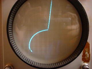
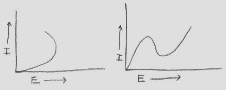
Visable on the curve tracer, is a negative resistance curve that could be obtained from several different pieces of iron pyrites (with much finicky adjusting). Not all pieces of iron pyrites seem to work. I found that the kind with a lot of little crystal formations worked the best. The fact that several pieces that I happened to have, worked, makes it appear that a working crystal is not all that rare. It was nice to realize that this phenomenon was not just the result of some fluky "one in a trillion" find.
Adjustment of the catwhisker is very critical however, and requires a lot of patience in comparison to adjusting as a receiving detector. For every spot that produces a useable negative resistance, there are many many settings that would make an excellent detector for reception.
As the curve tracer photo above shows, the negative resistance region is in the reverse bias portion of the curve at approximately -8 volts and 8 ma. Some of the articles refer to this as being like a tunnel diode. It is true in the sense of having negative resistance, but it is in fact a different type of negative resistance. This is ok since both types of negative resistance can have the effect of gain, supplying enough energy to an LC circuit for it to become an oscillator. The negative resistance portion of the curve is obtained when negative voltage is applied to the catwhisker.
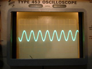
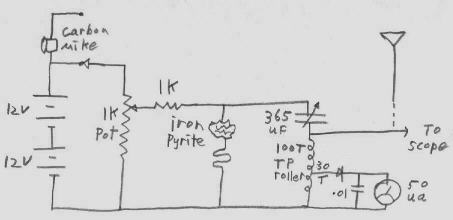
The circuit shown is all that is necessary to produce a continuous wave signal in the broadcast band. It seemed difficult to get it to operate above 2mhz but was easy to get it running at anything below that, including audio frequencies. It seems to prefer certain LC ratios better than others. In the case of the broadcast band, A 365pf variable capacitor worked well with a 190uh coil (100 turns on a TP roller).
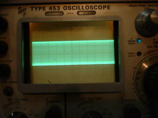
Once a good piece of iron pyrites is selected, the curve tracer is not necessary for making circuit adjustments. A meter or oscilloscope, to indicate that the the circuit is oscillating, is the most important tool in making circuit adjustments.
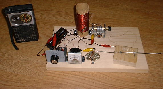
I found it extremely difficult to get steady oscillations with conventional type catwhiskers. I tried a simple idea that I call the "Tone Arm" catwhisker because of it's resemblance to the tone arm of a phonograph. With it I can often obtain steady oscillations that last indefinite periods of time (several minutes anyway). This catwhisker also worked very well when used with a normal crystal set. I got good results using #30 gauge copper or #28gauge steel wire for the catwhisker. Those sizes are what I happened to have handy.
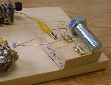
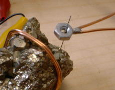
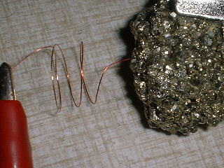
To connect to the iron pyrites, several turns of bare #18 copper wire were wrapped around it and twisted tight. I have always found this kind of arrangement to be as good as anything. It has never seemed that casting in molten metal etc. is at all necessary for any of the crystals I have ever experimented with. Another copper wire over the crystal and wrapped around a couple of screws in the board works well for mounting the crystal.
The best way to get the circuit going is by setting the 1k pot to a mid point and then patiently and carefully probing with the catwhisker. Catwhisker adjustment is by far the most critical part of the process. Many points will be found where the meter will jump momentarily. These are good places to stop and try some fine adjusting, by gently nudging the wood block that supports the "tone Arm", for a steady meter indication. If nothing happens, the pot level is raised a bit and searching on the crystal continues. The ranges on the pot that work are fairly wide in relation to the complete range of the pot. This puts most of the burden of adjustment on simply searching the crystal. Use just the oscillation indicator for adjusting. Get the circuit oscillating and then tune it to a selected frequency on a nearby radio. Trying to adjust by listening to the the radio is futile because you would have to search the crystal for each of many many different tunings as well as each of many different pot settings. You can imagine how many combinations would have to be tried.