This project was sucessfully done earlier using iron pyrites (see Iron Pyrites Negative Resistance Oscillator) Iron Pyrites Negative Resistance Oscillator The heat treated galvanized device however, is much superior in ease of use, consistancy and is very easy to prepare. As with the Iron Pyrites oscillator, success with this experiment has been a very exciting experience for me as it represents the ability to build a simple homemade active semiconductor device. It is almost like making your own homemade transistor. This is an actual realization of some very old, and esoteric 1920's experiments, by W.H. Eccles, Greenleaf Pickard and Oleg Losev, that were so vaguely reported in a few articles that I have often wondered if in fact it had actually been done. Even so, I have always had an extreme fascination with those reports of being able to produce a continuous wave RF signal from a crude semiconductor matarial back in the very early days of radio. From my experiences in experimenting with negative resistance materials, I can now say that those experiments done in the early days of radio, appear to be valid factual reports.
My fascination led me to purchase an old Tektronix 575 curve tracer so I could study the curves of various materials that might have negative resistance or detector properties as used in crystal sets. The curve tracer is not necessary in order to make and use the negative resistance device and circuits as described below. It is instrumental however, in the evaluation and discovery of materials which posess unique electrical properties. The 575 is a vintage but great tool because it continuously shows the curve in real time as you manually manipulate the samples. This is what is needed in order to make observations while manually touching a piece of wire to a piece of material. I wanted to be able to display both the positive and negative portions of the curves simultaneously and so had to modify the curve tracer in order to do so.
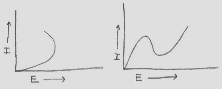
Some articles refer to this negative resistance as being like that displayed by a tunnel diode. It is true in the sense of having negative resistance, but it is in fact a different type of negative resistance. This is ok since both types of negative resistance can have the effect of gain, supplying enough energy to an LC circuit for it to become an oscillator.
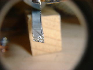
Making the galvanized sheet metal negative resistance device is very easy. Simply hold, using pliers, the end of a thin 1/8 inch wide strip of galvanized sheet metal, of the type used for furnace ducts, in the flame of a propane torch until it glowes bright red and shoots out whit hot flares. It is a good idea to do this out of doors and to avoid breathing any of the smoke or fumes. People who are knowledgeable about welding say that poisonus fumes are produced when welding galvanized metal. After cooling, small dark spots will appear, especially on the side opposite where the flame has struck. These dark spots are the main negative resistance areas. The catwhiskers tried were 28 gauge steel wire and 30 gauge copper wire. Both seemed to work well.
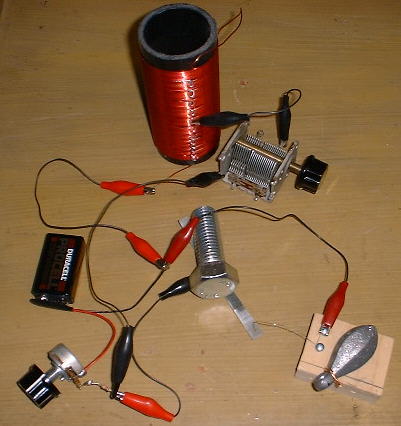
A good catwhisker arrangement can be made by putting two screws into a piece of wood about 1-1/2" square near the edge. A piece of #28 gauge steel wire can be wrapped around the two screws and cut to about 3" in length. The wire is then bent in an arch so that it lightly touches the heat treated metal as the block is moved around. A heavy weight on the block will make its position stable after making adjustments.
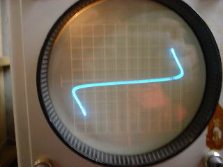
As can be seen on the curve tracer photo above, the curve can be quite symmetrical in both the negative and positive direction, although I sometimes would observe a somewhat asymmetrical curve. This picture was taken while the curve tracer was applying ac to the device. I had to modify the curve tracer so it could apply ac.
Oscillator circuits can be made that run easily from one 9v battery. It often seems easier to obtain steady oscillation when the catwhisker is biased negative with respect to the metal strip, but biasing in either direction can work.
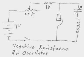
The circuit shown is all that is necessary to produce a continuous wave signal in the am broadcast band. It seemed difficult to get it to operate above 2mhz but was easy to get it running at anything below that, including audio frequencies. It seems to prefer certain LC ratios better than others. In the case of the am broadcast band, A 365pf variable capacitor worked well with 50 turns on a piece of 1 3/4" outside diameter abs pipe.
The trickiest part of getting this circuit to operate is to be able to tell when it is oscillating. The easiest way is to have an oscilloscope across the coil or across part of it with a tap. You simply make adjustments until you see the signal appear on the scope. It can also be done by adjusting the catwhisker while rocking the variable capacitor back and forth through its range and listening with an am receiver. This takes a bit more skill but it can be done. Another way to tell if it is oscillating is to put a diode and microameter across part of the coil. When a steady deflection of the meter is obtained, the variable capacitor can be tuned to the desired frequency using a receiver.
A good place to start making adjustments is with the pot set so that there is a total resistance of about 4k ohms including the 1k resistor. The only function of the 1k resistor is just to prevent a large amount of current flowing when the pot is set at zero resistance. Some settings of the catwhisker allow the circuit to oscillate over very wide variations of resistance (pot) settings.
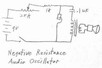
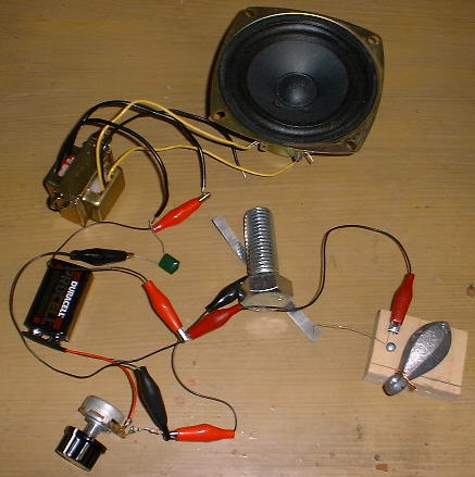
The audio oscillator is much easier to adjust and to get running. It is simply a matter of listening for a tone from the speaker or headset while making catwhisker adjustments. As with the RF oscillator, a good place to start is with the pot set so that there is a total resistance of about 4 kohms including the 1k resistor. Some settings of the catwhisker will make the circuit able to operate over a very wide range of resistance settings. You may find it easy to get the circuit going with just one 4.7k resistor in place of the pot and 1k resistor.
This audio oscillator circuit can use the 120 volt side of a 120 volt to 12 volt transformer or the 2k side of a 2k to 8 ohm transformer for the inductor. The output side of either of these transformers, 12 volt or 8 ohm respectively, can drive a speaker with enough volume to be heard across the room.
A pair of headphones of just about any impedance can be used in place of the speaker. A headset will present less of a load than a speaker and will result in a higher Q LC circuit. This can make it easier to obtain catwhisker settings that work well.
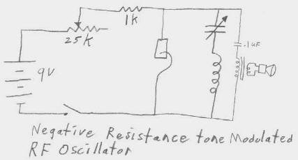
A tone modulated rf oscillator can be made by connecting both an rf LC circuit and an audio frequency LC circuit across the negative resistance. This circuit can oscillate at both rf and audio frequencies at the same time. It is possible to adjust the circuit by listening to the speaker or earphone and then tuning the variable capacitor untill it is heard through an am radio. With many settings, a loud, well modulated tone will be produced.
It is interesting to note that it is possible to get combinations of pot and catwhisker settings where the audio circuit will oscillate but the rf circuit will not, the rf circuit will oscillate but the audio frequency circuit will not or where both circuits oscillate at the same time to produce the tone modulated rf signal.
After the metal is cooled, many black spots are found, surrounded with snow white powdery zinc oxide. The white zinc oxide acts like an insulator and shows no continuity whatsoever. The black spots are where most of the negative resistance is found. Taking a wild guess, I would suggest the possibility of these dark spots being Zinc Ferrite Zn-Fe2-O4 or something similar, formed by the interaction of heat, oxygen and zinc, reacting with the surface of the iron. The side of the metal facing away from the flame would be more more likely to be in contact with oxygen than the side facing the flame. That may be why I seem to find more good negative resistance spots on that side. Zinc ferrite is described in the Handbook of Chemistry and Physics as a black material. It would appear that zinc is playing an important role in the negative resistance. It stands to reason since zincite is mentioned in early radio articles, as one of the best negative resistance materials. It would be interesting to see what the curve, exhibited by zincite is like but I have yet to visit a rock & mineral shop that has a piece of zincite available. Perhaps the performance of the heat treated galvanized sheet metal is good enough to satisfy concerns about obtaining zincite.