I have found that building negative resistance audio amplifiers, especially for crystal sets, can be a challenge owing to the fact that their gain is greatly affected by their input and output impedances and also because of their tendacy to act as oscillators. I find that building a broadband audio amplifier is easy only if the amplifier is driving a pure resistive load. Inductive loads such as a transformer or headset, which are usually the easiest way to make use of this gain, present varying impedances over the audio spectrum. I have had some success building negative resistance audio amplifiers that only produce gain into a headset over a narrow audio bandwidth. In addition, negative resistance amplifiers do not seem well suited for amplifying the audio output from a crystal set because of the low impedance that is usually required to drive the amplifier.
Using a negative resistance amplifier to amplify an RF signal however, is a much more straightforward task as only one frequency need be amplified and the impedances on the input and output can be easily chosen by using tap points on tuning circuits. An effective AM broadcast band RF signal amplifier can easily be made using the same homemade negative resistance device as is used to build the negative resistance oscillators written about earlier. This RF amplifier, is made with a simple homemade semiconductor device and uses no tubes or transistors. It can be connected to crystal set circuits to amplify the signal from the antenna or to make them into regenerative receivers. The main reason for building the receiver circuits described here is for the fun and satisfaction of doing it with a simple home made amplification device. To find out more details, about this homemade zinc negative resistance device, see:Zinc Negative Resistance Oscillator
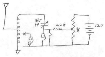
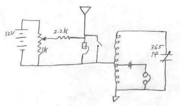
Two circuit configurations are shown below. The coil is wound on 1 1/2 abs pipe with taps every ten turns. The variable capacitor and detector diode tap points should be chosen for best band coverage and optimal headset volume.
These amplified circuits seem to work best with lower strength radio signals. In my location, there are a couple of very close radio stations that just tend to overwhelm the circuit. In order to simulate weaker signals, I have been using a 12 to 15 foot antenna wire strung up across the ceiling of my basement room. With the RF amplifier connected, I can hear stations through the small indor antenna at a level similar to that of using a much larger and higher outdoor antenna. It is sometimes possible, especially with the regenerative configuration, to hear the audio hetrodyne with the incoming signals.
I also tried using this amplifier on a friends crystal set located where there are no strong signals. I was able to clearly hear and understand a station that was otherwise too weak to be intelligable.
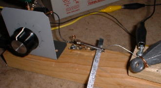
Making the galvanized sheet metal negative resistance device is very easy. Simply hold, using pliers, the end of a thin 1/4 inch wide strip of galvanized sheet metal, of the type used for furnace ducts, in the flame of a propane torch until it glowes bright red and shoots out whit hot flares. It is a good idea to do this out of doors and to avoid breathing any of the smoke or fumes. People who are knowledgeable about welding say that poisonus fumes are produced when welding galvanized metal. After cooling, small dark spots will appear, especially on the side opposite where the flame has struck. These dark spots are the main negative resistance areas.
A good catwhisker arrangement can be made by putting two screws into a piece of wood about 1-1/2" square near the edge. A piece of #28 gauge steel wire can be wrapped around the two screws and cut to about 3" in length. The wire is then bent in an arch so that it lightly touches the heat treated metal as the block is moved around. A heavy weight on the block will make its position stable after making adjustments.
For this amplifier to be effective, the optimum point, where the antenna taps into the coil, should be found. Negative resistance amplifiers are very fussy about the impedances they are connected to. One part of the band seems to require a different tap point than another part of the band. Each time a different station is tuned, different antenna tap points should be tried. I have had good success adjusting the circuit as follows. Close the switch across the zinc device. This disables the amplification and makes the circuit as a normal crystal set. Choose a point on the coil and tap the antenna into it there. Adjust the variable capacitor until you hear the station that you want. Open the switch, enabling the gain, and move the catwhisker around while at the same time varying the bias pot. When you find a catwhisker spot that makes a sudden jump in volume or hetrodyne type of sound, leave it there and make adjustments to the pot and variable capacitor for optimum volume. If you don't have much success, try connecting the antenna to a different tap point on the coil and make the above adjustments again. Certain settings of the pot will sometimes cause distortion. The idea is to adjust the pot for the highest volume without a lot of signal distortion. With some practice you should be able to get impressively higher volume levels than what can be obtained when the gain is disabled.
The configuration that amplifies the antenna signal was shown in a very excellent two part article from The Wireless World and Radio Review October 1, 1924 and October 8, 1924 entitled "The Crystal As A Generator And Amplifier" by Victor Gabel. The article also includes several regenerative receiver circuits that utilize the negative resistance device for both RF amplification and detection. I have had success in the past building similar regenerative receiver circuits but greater headset volume is produced when using an additional detector diode, as I have described here. This article was found by Ken Ladd and is absolutely the best article I have seen on the very esoteric subject of oscillating crystal experiments performed in the 1920's. What a find this was!!! This article is very generous with explanation, details and schematics. There is at present a question regarding the ability to mass distribute copies of this article because of copyright but it is being looked into.
I must point out that the term "oscillating crystals", as used here, should not be confused with the piezo electric resonant crystals used nowdays to control oscillator frequencies. The early negative resistance experiments were performed using the same crystal substances as were used to make detectors.
Most of the experiments in many of the old 1920's article talk about the use of zincite as the most successful negative resistance material. Some articles state that the zincite must be that which is obtained from one place in the world, Franklin N.J. It is my opinion after experimenting, that the simple home prepared heat treated galvanized sheet metal can be used in most if not all cases, as a substitute for the zincite.
When reading various articles about the performance of crystal sets, one must be careful about taking a lot of performance claims to seriously, owing to the many many undocumented variables. Many will report about how something works as a detector for example, but no information or definition is given to how powerful of station is being listened to or how far away it is. One person might write about how a certain material works well as a crystal set detector but for all we know, they may be one block from a 50 kw radio station. Another report may be written by a person who was 20 miles from the nearest station. Under the circumstances of being one block from a 50 kw station, almost anything would work as a detector; you would hear something, almost no matter what kind of circuit or antenna is tried. I once knew a person who lived next to a 50 kw am broadcast station. He was always hearing the station while using his normal telephone. Many of the reports given by individuals about how well a crystal set works for them, are short on documentation about their location and circumstances concerning the strength of the signal being received.
There are also numerous claims in vintage literature, of being able to get amplification in a crystal set by connecting a battery to the circuit or detector in some way or another. It is probable that many of these increases in volume are not from amplification, but merely the result of making the detector more efficient with biasing. Many types of detectors require a small bias voltage across them in order for them to work well. Getting a louder signal when a battery is connected has probably made many think that the circuit is amplifying when in reality, it may have just been loosing less of the signal than it was before.
I wish to clarify these points and assure the reader of this article, that all observations of gain in the circuits described herin, have been made with the above points in mind.
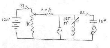
Another configuration for using the negative resistance device is to use it as a simple CW RF oscillator or tone modulated RF oscillator. See circuit below. Through a nearby crystal set it is possible to hear this oscillator as a hetrodyne with incoming signals or as an audio tone. Why would anyone want to hear a hetrodyne with an incoming broadcast station? Mainly for the rush it gives when you realize you have just made a tiny transmitter using a homemade semiconductor.
Closing S2 puts the circuit in the tone modulated RF mode by including the phones and the .1uf capacitor. This forms an audio frequency LC circuit. In this configuration, the circuit can oscillate at both an RF and an audio frequency at the same time. The tone can be easily heard on a properly tuned nearby crystal set.
The tone modulated mode makes adjustment of the catwhisker easy when listening for an audio tone in the phones. This tone modulated circuit makes a very effective code practice oscillator if S1 is replaced with a key. You can hear the tone through the phones in the circuit or through a nearby radio. An element of excitement would be added to the teaching of morse code to students when they realize they are actually hearing the signal from a tiny nearby transmitter. Take out the RF LC part of the circuit, and you still have an audio code practice oscillator by listening through the phones.
When making adjustments, it is necessary to listen for both an audio tone in the phones and in the nearby crystal set. This is because some settings can cause just the audio portion of the circuit to oscillate. Other settings may cause just the RF portion to oscillate. Hearing the tone in the phones and the nearby crystal set indicates that both audio and RF circuits are oscillating. When this condition is achieved, open S1 and then S2. When you close S1 again and you will usually have a CW RF oscillator which can be heard on the nearby crystal set. Of course the variable capacitor must be tuned to adjust the oscillator frequency to the crystal set frequency. The oscillator coil may need to be set near enough to the crystal set that it interacts with the crystal set coil. Opening S2 without opening S1 first, has a tendacy to destroy the negative resistance setting.