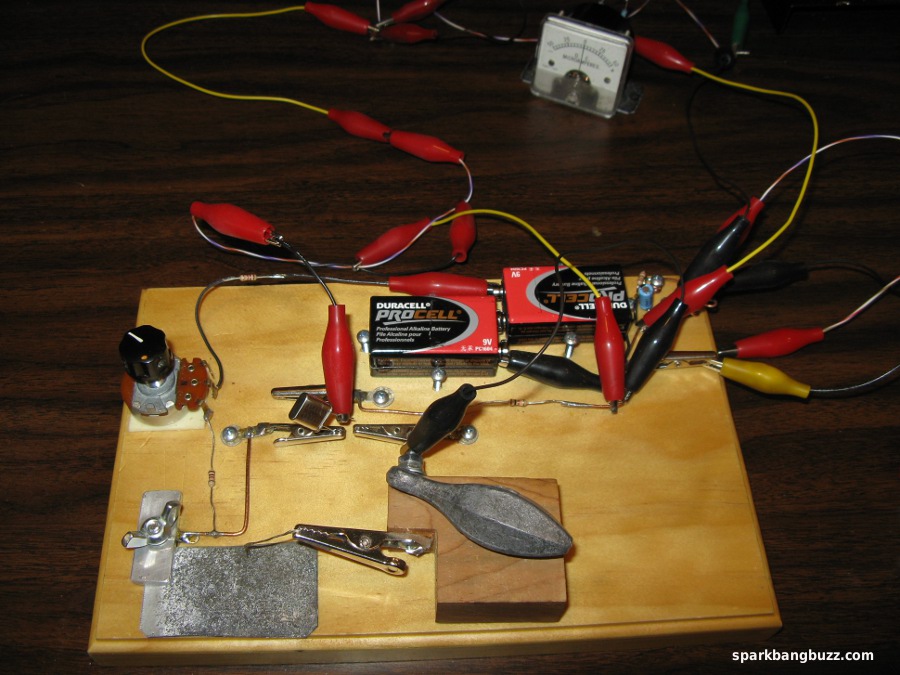
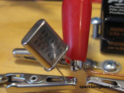
This 20 meter zinc transmitter is just like the 80 and 40 meter zinc transmitters that I described previously in the links above except the crystal is 14.318 mhz and the antenna and ground wires are proportionately shorter.
I was able to easily hear the 80 meter and 40 meter zinc transmitters from a distance of 5 miles. It is easy to hear this 20 meter transmitter from a distance of about 1 1/2 miles but it is winter and difficult to get to my usual 5 mile monitoring location up on the mountain. I may have to wait until spring, but I am optimistic about being able to hear this transmitter from that same 5 mile location.
When I published my first zinc negative resistance article in 2001, I was not sure this zinc diode could oscillate above 2 mhz until one of its readers, R. A. Nickel W9RAN informed me that he had successfully made a zinc crystal oscillator run at 3.5 mhz (80 meter band). That inspired further experimentation on my part with making zinc diode ham band transmitters. These transmitters typically put out just 50 to 100 microwatts but imagine how fun it has been since then, making an 80 meter CW transmitter without using any tubes or transistors and then doing it again on 40 meters (7 mhz). Now It is even working on 20 meters (14 mhz). This all represents an incredible amount of fun, coming from a few microwatts!
The transmitting antenna is a 25 foot wire run through a hole in the wall and supported by a tree. The ground is a 16 feet 4 inch long wire run through a hole in the wall and laid on the ground. The antenna is 3/8 wave long and the ground wire is 1/4 wave long. The 3/8 wave antenna wire represents a good compromise between the high impedance of 1/2 wave and the low impedance of 1/4 wave. This makes it easy to load up.
The smaller size of the 20 meter antenna makes it lower to the ground in proportion to buildings etc. and it seems to be more difficult to hear its signal in some locations in town. However, my handheld receiver has bars to indicate signal strength and I get bar indications with the 20 meter signal that are comparable to or better than those obtained on 40 and 80 meters, while monitoring from the street about 75 feet in front of my house.
Of course any antenna configuration can be tried with this transmitter but I am describing this exact configuration including the wire laid on the ground, because it seems to work well enough and it makes all the variables repeatable for anyone who may be interested in replicating this project.
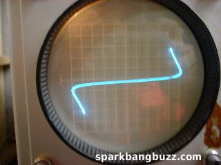
Typical curve of a homemade zinc negative resistance device. Horizontal represents voltage and vertical represents current. There is more info about the making of this device in my previous zinc negative resistance articles.
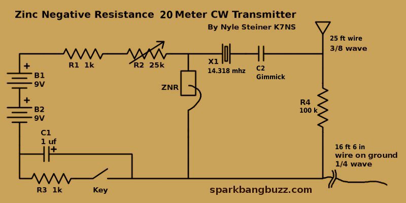
Schematic of zinc negative resistance 20 meter CW transmitter shown above.
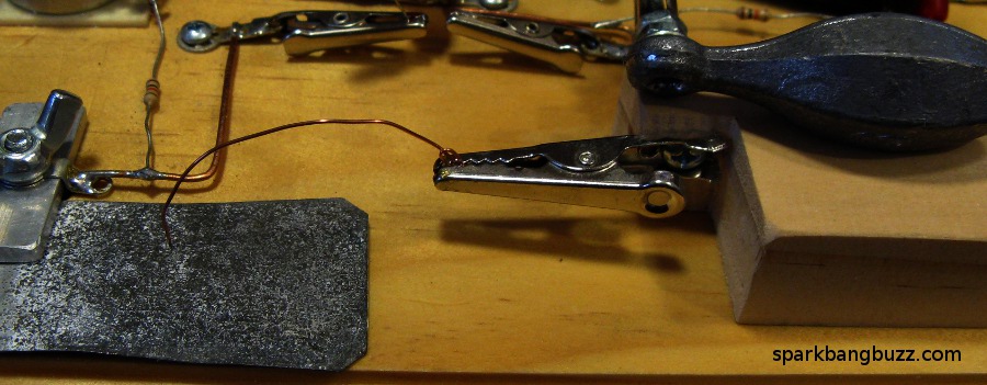
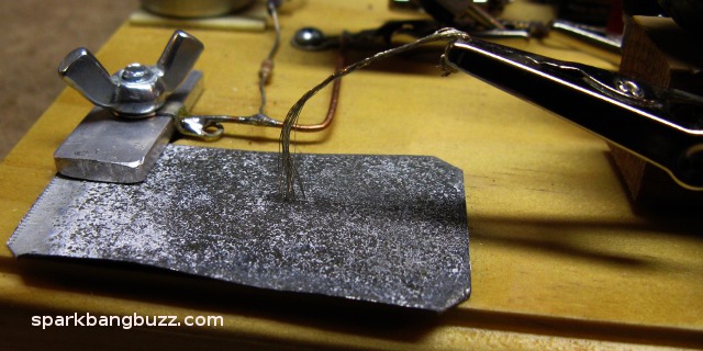
ZNR in the diagram is the zinc negative resistance device. It seems easier to get good catwhisker settings when the piece of heat treated zinc sheet metal is biased positive in relation to the catwhisker.
Good catwhisker settings at 14 mhz seem to be fewer and farther between than they are at lower frequencies and the CW tone stability suffers more at 14 mhz, but that is a small distraction from the satisfaction of being able to make a 20 meter transmitter from a simple homemade semiconductor device.
20 meters appears to be a good place to experiment with catwhisker optimization. I have experimented with multiple wire catwhiskers and more recently with a single 24 gauge copper wire, both with a sharp end and with the end filed flat. The copper wire filed flat on the end seems to work as well as anything. It may be possible that a sharp end could have the tendency to slide off from peaked microscopic sensitive spots. In any event, it is good to experiment with different catwhisker configurations and pressure as I believe there is still much to be learned in this area.
Start by adjusting the catwhisker and R2 (25k pot) simultaneously until some oscillation is heard on the receiver. Then adjust R2 by itself for optimum power output and oscillation reliability (see tuning meter below). If a good steady oscillation is not obtained, try again by adjusting the catwhisker and R2 simultaneously again.
The capacitor C2 at this frequency is just a "Gimmick" made by wrapping one clip lead about two turns around another clip lead.
The 100k resistor R4 provides a DC path between the antenna and ground. This prevents electrostatic charge buildup and discharge which can destroy the catwhisker setting.
C1 and R3 greatly improve the keying reliability of the transmitter. Without them, there are many catwhisker settings that stop working after opening and closing the key. Almost all catwhisker settings seem to key much more reliably when C1 and R3 are in the circuit.
A 25k pot placed in parallel with the key can reduce chirp if it's resistance is set just high enough for the circuit to stop oscillating when the key is up. This reduces the variations in power dissipation across the zinc device, when keying.
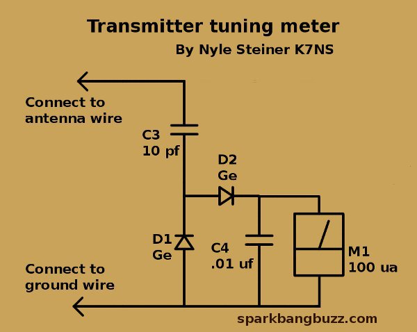
This meter circuit was drawn separately from the transmitter circuit for clarity. It is connected between the antenna and ground wire.
I call this a tuning meter because it is neither an SWR meter nor a power meter. It simply shows relative voltage signal level across the antenna-ground feed point. The objective is to get the highest reading possible consistent with good signal stability and keying reliability while making adjustments to the zinc negative resistance device, R2 and C2.
With the 20 meter transmitter I usually get meter readings that vary between 10 to 30 ua.
I also like to call this meter a "Bottom Line Meter" because after all that may be accomplished by using a fancy SWR meter and power meter, the bottom line is that maximum signal voltage represents maximum power to the antenna. It just doesn't tell you how much.
AS LONG AS THE FREQUENCY AND THE ANTENNA-GROUND SYSTEM REMAIN THE SAME, A PEAK READING ON THIS METER WILL INDICATE MAXIMUM SIGNAL STRENGTH BEING FED TO THE ANTENNA.
I almost always get good results using this "Bottom Line" method of tuning antennas, whether it be tiny zinc transmitters or conventional transmitters. During one period of time while using this antenna system with a more conventional transmitter, I was able to consistently make at least one contact a day across the pacific ocean from Los Angeles using roughly 1/2 of a watt.
This antenna-ground system and tuning method may not win an efficiency contest but I think I can safely say that it works reasonably well.
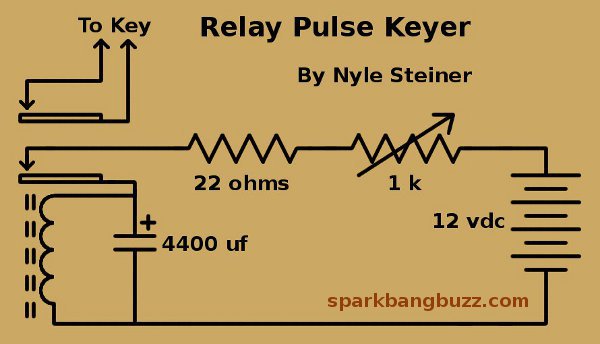
This circuit keys the transmitter about once every second to make the signal easy to identify. This type of keyer made it possible to do the experiment, including keying the transmitter, without having any transistors whatsoever in the entire transmitting system.
It is a relay connected as a buzzer but with a huge capacitor across the coil to make it run slow (about one pulse per second). The 1k pot can adjust the duty cycle to approx 20 to 40 percent. In this case a 4400 uf capacitor is used but the size of this capacitor has to be determined by experiment depending on the relay used.