Update March 23 2008. 1.3 mile to 3.5 mile distance.
Update April 28 2008. 3.5 mile to 5 mile distance.
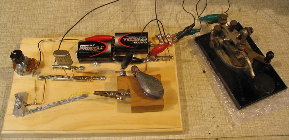
While listening to a hand size short wave receiver with BFO (Degen 1103), I could hear the flea powered transmitter pictured above from a distance of 5 miles (straight line GPS distance).
Transmitter antenna was a random length wire run through a hole in the wall and thrown into a tree. Ground was a clip lead connected to the screw of an electrical outlet cover.

The snow has finally receded enough that I could get to this 5 mile distant location up the mountain. From here, I could hear the transmitter located in the small town below.
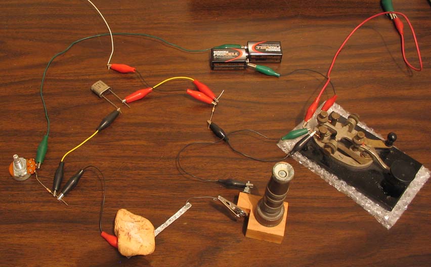
This 80 meter transmitter using simpler construction, is identical to the one pictured above and works just about as well.
Notice the "Rock Stable" mount for the zinc strip.
Schematic of CW transmitters shown above.
The 10k resistor provides a dc path from antenna to ground. This helps to prevent static discharges from the antenna. A jumper across the 10k resistor is usually necessary when running this transmitter without an antenna.
This is a continuation of my previous article on negative resistance oscillators built using the homemade zinc negative resistance diode.
My first article mainly described zinc negative resistance LC oscillators that I had made to run anywhere from sub audio up to 2 mhz. I had not put a lot of effort into making a zinc oscillator run above 2 mhz nor did I have much faith that one could run above that frequency. After all, this zinc negative resistance device was already running much faster than I had ever seen any unijunction transistor run back in the 1970's when unijunction transistors were popular. Making these zinc negative resistance oscillators was a very exciting experience but it left me with pipe dreams of being able to make them run on a ham band above 160 meters.
Many of the rewards from writing web page articles come in the form of emails and gems of information from readers. I recently received an email from Robert Nickels W9RAN who had read my first article about the zinc oscillator. He reported success in making a zinc negative resistance crystal oscillator run at 3.579 mhz (middle of 80 meter ham band). I had not tried using crystals with the zinc oscillator in the past and was excited to hear of his success at 3.58 mhz.
As you can imagine, I soon had my zinc negative resistance stuff back out on the table along with my box of collected crystals. I also had no difficulty in getting 80 meter crystals to oscillate. In fact with some experimenting and circuit refinement, I soon had a zinc crystal oscillator running at 10 mhz.
If I could now figure out how to couple a zinc oscillator to an antenna, I could experience the thrill of being able to transmit on a ham band using just a homemade semiconductor and no tubes or transistors.
The schematic above and the section below "Coupling The Oscillator To An Antenna" describe how I was able couple the zinc oscillator to an antenna making it into a transmitter.
The diagram above shows the zinc negative resistance crystal oscillator. C1 is usually not necessary for 80 meter crystals (3.5 - 4 mhz) but C1 makes it much easier with higher frequency crystals such as 7 mh to 10 mhz.
As can be seen above, it is now routine to make an 80 meter (3.5 to 4 mhz) cw transmitter using a zinc negative resistance crystal oscillator. At this point I have been able to make zinc oscillators run up to about 13 mhz but stable and reliable operation for a 40 meter (7 mhz) transmitter seems more difficult. A 40 meter transmitter is definitely possible but so far most of my effort has been concentrated on making an 80 meter transmitter.
I will report later on making a 40 meter transmitter if I can get one working well some time.
I have identified some key refinements that help make these zinc oscillators able to run at frequencies in excess of 10 mhz. The explanation is straightforward and intuitive. No mural of mathematical hieroglyphics is necessary here. I don't speak that language anyway.
1: These zinc negative resistance oscillators are basically working as relaxation oscillators. They will run just fine using just a capacitance across the zinc diode. In fact I was able to obtain frequencies up to about 13 mhz just by running an oscillator in the relaxation oscillator mode.
When a crystal is placed across the zinc diode, a relaxation oscillator is formed from the capacitance of the crystal and the charging resistance comprised of the 25k pot and 1k resistor. This relaxation oscillator can easily run at frequencies below the crystal frequency while the crystal remains inactive. If the frequency of this relaxation oscillator is increased to match that of the crystal resonant frequency, the crystal pops into action and has a tendency to lock the oscillator to the crystal frequency. The relaxation oscillator must be able to run at the crystal frequency by it's self in order to activate the crystal.
Difficulty is encountered when you have a high frequency crystal with too much built in capacitance to allow the relaxation oscillator to reach the crystal resonant frequency. By putting in a very small capacitance of several pf C1 in series with the crystal, the overall capacitance is made small enough to allow the relaxation oscillator to reach the higher crystal frequencies.
It seems that crystals up to about 4 mhz work well when connected directly across the zinc diode whereas higher frequency crystals around 7 to 10 mhz work much easier with C1 in series. I have been able to make C1 just by disconnecting one of the crystal clip leads and laying it over the point where it was previously connected. A couple of insulated wires two to three inches long twisted together also work well for C1.
2: I find it easier to get these oscillators running by using 18 vdc from two nine volt batteries in series instead of using just 9 vdc from one battery. With a given amount of current through the charging pot and 1k resistor, the capacitor can charge faster when using 18 volts because it is charging more on the steeper part of the capacitance charge curve.
3: It seems much easier to get these oscillators running if the zinc strip is positive with respect to the catwhisker. This is a bit interesting since these zinc negative resistance devices display very similar curves in both the positive and negative direction.
4: I have been having great success at using a multiple tip catwhisker. I take a piece of stranded 26 gauge wire, strip 1/4" insulation from the end and arrange the protruding wires in the shape of a fan. I then cut the end of the fan straight with a pair of scissors. When using this as a catwhisker, I find the time looking for good spots on the zinc strip much shorter.
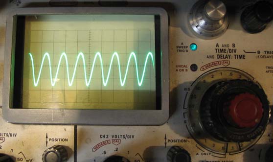
Zinc negative resistance crystal oscillator running at 7.038 mhz.
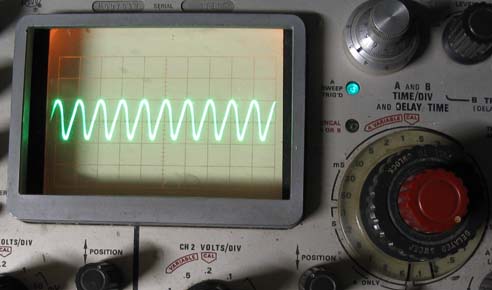
Zinc negative resistance crystal oscillator running at 10 mhz.
Realizing that the zinc negative resistance oscillator can easily run at ham band frequencies was exciting but I still had to figure out a way of coupling it to an antenna. As mentioned above, any extra capacitance placed across the crystal will swamp the relaxation oscillator and an antenna has plenty of capacitance.
I had success by coupling the antenna to the ground side of the crystal and running the signal through the crystal into the antenna as shown in the 80 meter transmitter schematic above. The antenna now provides a load for the crystal to work into instead of swamping the circuit. The 10k resistor is simply a dc path to reduce static buildup and discharges from the antenna. A jumper across the 10k resistor is usually necessary when running the 80 meter transmitter without an antenna.
My favorite antenna is a plain old random length long wire run through a hole in the wall and thrown into a tree. I love the simplicity, no coax, no separate lead in, no bother with swr etc. Each different length of wire will present its own impedance value to the transmitter. If you can match and drive whatever impedance the random length wire is presenting, it will radiate and you are ready to go.
Contrary to what many articles on antennas seem to imply, an antenna does not need to be resonant in order to radiate a good signal. I believe that the biggest reason so much effort is put into making antennas resonant is because the resonant condition is part of a total configuration designed to present a 50 ohm impedance to the transmitter. 50 ohms is what most modern transmitters are designed to match. In the good ole days, many transmitters could be adjusted to drive almost any impedance whether it be 50 ohm coax, a random length of wire or even a light bulb dummy load.
In years past, I have had many amazing cw qso's across the pacific ocean and across the united states using less than one watt and a wire thrown into a tree. One one occasion while using less than one watt near Los Angeles, I was having a qso with a ham in Japan using the random length wire thrown into a tree. He said that I sounded like 100 watts into a dipole.
The output power from a zinc negative resistance transmitter is very small (usually less than one milliwatt) but as pointed out above, a signal with very little power can be heard at unbelievable distances.
It can be difficult to determine how much power is being fed to random length long wire antennas because of their wide variations of impedance but I believe you can get a reasonable idea of how much power a transmitter will put into an antenna by driving resistive loads and calculating the power dissipated by them. The zinc negative resistance transmitter seems to be able to drive a wide range of load impedances reasonably well.
Different catwhisker settings produce various negative resistance characteristics and therefore have an effect on the amplitude of oscillations and amount of output power. Power output into a load seems to depend more upon a good catwhisker setting than it does upon an exact impedance match with the load. Almost any ballpark load impedance from an antenna therefore appears to be suitable for this transmitter.
I experimented with several output load resistor values in place of the antenna to get an idea of how much power can be obtained from the 80 meter zinc transmitter. Using a 3579 khz crystal, I took measurements with four separate resistor load values placed between the antenna connection point and ground: 56 ohms, 150 ohms, 220 ohms and 510 ohms. The output power was derived by reading the peak to peak voltage across the load with an oscilloscope, dividing it by two and multiplying by .707 to get the rms voltage value. The rms voltage value was then squared and divided by the load resistance according to ohms law to obtain the power being fed into the load resistor.
56 Ohms: Average 41.95 micro watts
80 mv = 14.3 micro watts
100 mv = 22.3 micro watts
200 mv = 89.25 micro watts
150 Ohms: Average 79.74 micro watts
240 mv = 48 micro watts
250 mv = 52 micro watts
300 mv = 75 micro watts
330 mv = 90.7 micro watts
400 mv = 133 micro watts
220 Ohms: Average 65.16 micro watts
200 mv = 22.7 micro watts
380 mv = 82 micro watts
400 mv = 90.8 micro watts
510 Ohms: Average 73.3 micro watts
400 mv = 39 micro watts
500 mv = 61 micro watts
700 mv = 120 micro watts
I do not believe there was enough inductance in the resistors or capacitance in the scope probe to adversely effect the quality of the above measurements. The output voltage readings were essentially the same when the scope probe was switched between X1 and X10.
I was able to obtain higher levels of power output using a 1 mhz crystal. A few measurements were in excess of 1000 micro watts. In other words, a whopping 1 milliwatt.
I personally would not complain anyway about a few warbles or chirps especially in light of the tiny output power level and massive thrill level that this transmitter delivers using a simple homemade semiconductor.